Introduction to the transistor
The purpose of this text is to give a basic understanding of the behaviour of a transistor. It is made for readers with some knowledge about electricity: voltage, current, resistors, batteries, Ohm's law. Technical problems like non-linearity and behaviour under high frequencies are not talked about.
Description of the transistor
The transistor is a component with 3 electric wires coming out of it. They are named B (base), C (collector), and E (emitter).
This is a drawing of the BC 547 transistor, four times bigger:

Such a transistor costs $0.3 in electric components stores.
Here is a classic drawing for a transistor inside electronic diagrams:

How it is used

The electronic diagrams corresponding to figures 1, 2 and 3 are figures 4, 5 and 6:

Note: For those who would like to try out these diagrams, one sole battery of 9 Volts can replace the two batteries (fig. 7 and 8):

Be careful for the polarity: put the positive wire and the negative wire of the battery on the right place. The direction of the current is very important for a transistor.
The BC 547 is a somewhat weak transistor to make a lamp light up. Perhaps you will get better results using a stronger transistor, for example the BD 649. Here is a drawing of it, two times bigger:

As a beginner, by making wiring errors or making the transistor dissipate too much heat, you will probably burn a few of them. That's normal.
The reason why one subtracts systematically 0.7 Volts from the UBE tension is that bipolar transistors contain sort of "parasite" diode. The tension that must be subtracted depends on the sort of semiconductor: 0.7 Volts for silicon, 0.2 Volts for germanium.

The purpose of this text is to give a basic understanding of the behaviour of a transistor. It is made for readers with some knowledge about electricity: voltage, current, resistors, batteries, Ohm's law. Technical problems like non-linearity and behaviour under high frequencies are not talked about.
Description of the transistor
The transistor is a component with 3 electric wires coming out of it. They are named B (base), C (collector), and E (emitter).
This is a drawing of the BC 547 transistor, four times bigger:

Such a transistor costs $0.3 in electric components stores.
Here is a classic drawing for a transistor inside electronic diagrams:

How it is used
- If one connects a tension source between the wires C and E, the transistor will not let any current trough (fig. 1).
- But between B and E there is a shortcut. If one wants to make a given current go trough B and E, one must use a tension source and a resistor (fig. 2).
- If one sends a current of IB amperes between B and E, then the resistor will allow a current of IC = ß . IB amperes pass between C et E (fig. 3). In this case, ß is about 100.

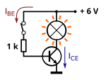
The electronic diagrams corresponding to figures 1, 2 and 3 are figures 4, 5 and 6:

Note: For those who would like to try out these diagrams, one sole battery of 9 Volts can replace the two batteries (fig. 7 and 8):

Be careful for the polarity: put the positive wire and the negative wire of the battery on the right place. The direction of the current is very important for a transistor.
The BC 547 is a somewhat weak transistor to make a lamp light up. Perhaps you will get better results using a stronger transistor, for example the BD 649. Here is a drawing of it, two times bigger:

As a beginner, by making wiring errors or making the transistor dissipate too much heat, you will probably burn a few of them. That's normal.
The reason why one subtracts systematically 0.7 Volts from the UBE tension is that bipolar transistors contain sort of "parasite" diode. The tension that must be subtracted depends on the sort of semiconductor: 0.7 Volts for silicon, 0.2 Volts for germanium.


